|
<< Prev
[1]
[2]
Next >>
 |
Step 1
In this tutorial we will demonstrate the Shrink Wrapping plug-in action. This action
uses the Visualisation Toolkit library to provide the marching cubes algorithm for
rendering an iso-surface in a potential field. The field is generated by using OpenFX's
mesh topology to define the potential field. This can be done using either a vertex, an edge
or a face.
The idea of the action is to place a volume filling cubic array of points (a point cloud)
around all the selected
vertices and then to use this array to build a surface mesh that lies in this
within this volume of points and lies at a place where the specified equi-potential takes the
value zero.
The shape of this surface is defined by the choice of element (vertex, line, face) to be
wrapped and the distance from the element that is defined to be the location of the zero potential
value.
The action requires that this distance is specifed in terms of the 'units' of scale in the model,
so the first thing that any user of this tool must do is make sure they are aware of the scaling
in use. The best way to see how this tool works is to start with a few simple shapes
and look at the results of the application of the tool.
|
 |
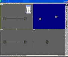
Step 2
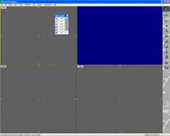
We will start with two vertices, and link them together with an edge so that we
can see the effect of shrinking around vertices and around edges.
The vertex on the left is circled in red, the coordinates dialog is used to set the coordinate
origin at the position of this vertex. The 3D cursor (circled in yellow) is
then placed at a distance along the x axis and the coordinates dialog used to
make the distance between vertex and 3D cursor (current location)
1 (one) unit. The hold point for this model is indicated at the yellow cross.
The second vertex is located approximately 1 unit to the right of the second vertex.
(This action requires at lease two vertices to be selected.)
|
 |
Step 3
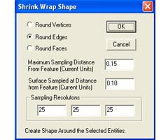
We can now try the shrink wrap tool. Bring up the dialog Action->PlugIn_Actions->Shrink_Wrap.
This brings up the dialog. Click on the button that says "Round Vertices". The default
maximum sampling distance and surface sample distance will suffice for this first step. Note that
at the bottom of the dialog are 3 boxes to enter the samping resolutions. These 3 numbers
dictate the coarsness (or finenss of the mesh.)
To understand the sampling resolution: Think of the X (horiziontal direction) the default is for
25 mesh points to be spaced out along this dimension to enclose the whole span of
the selected vertices (in the X direction) and an additional distance of the "Maximim Sampling Distance
From Feature". The location of the surface will be drawn at a distance of the "Surface Sampled at Distance
From Feature". A fair choice of these paramters will depend on the dimensions of the model itself but
a Sampled distance of about 25% of the maximum sampling distance will give a nice smooth surface around
the vertices.
|
 |
Step 4
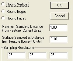
Back to the example. With the "Round Vertex" action selected - Click OK. The resulting mesh has
been created around the two vertices. It is not very smooth because the 25x25x25 grid points
cover a very large region of space out to a range of 1.0. If we repeat the process using a surface
distance of 0.7 the mesh surface will be built at a much greater distance.
|
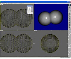 |
Step 5
This shows the result when we set a range of 1.0 and surface distance of 0.7 instead of 0.1
(again using the "Round Vertex" option.) You will see that the surface is drawn much further
away from the vertices and it looks like two spheres intersection. However if you check out
the mesh in detail you will see it is a single surface. Essentially it is mesh that maps out
the value of a potential field emminating from the two vertices.
|
Tutorial written by Stuart
<< Prev
[1]
[2]
Next >>
|